The VE.Direct protocol
I use a couple of Victron devices in my camper for charging and measuring the batteries. Some of them support the VE.direct protocol, which can be used to gather measurement- and status info from the device. When I decided to build a data logger for the bus, I did some digging to gather all the information needed to implement support for this protocol properly, including checksum verification and device identification. Although Victron did quite a good job documenting this protocol, I found that the information was scattered all over the internet. In an attempt to make it easier for other people who want to build something with VE.direct support (or just want to know more about it for educational reasons), I put everything I know about the protocol on this page. If you don’t know if your device supports VE.Direct, you can check the whitepaper “Datacommunication with Victron Energy products“. Victron’s documentation on the VE.direct protocol can be downloaded here.
Mechanical
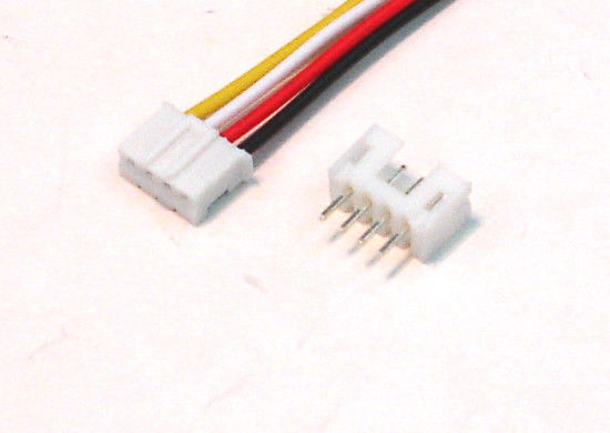
VE.Direct uses 4-pin JST connectors. The device has a male connector, so you will need a 4-pin female JST connector for your cable. These connectors come in different sizes and different number of pins. You will need the 4-pin JST PH 2.0 type. They can be bought from Amazon, eBay, Aliexpress and probably at your local electronics shop, too.
Please note that RX and TX are specified from the point of view of the device itself. So for the ‘producers’ of VE.direct data (such as BMV’s and MPPT’s) the pinout is like this:
Pin 1 – GND
Pin 2 – RX
Pin 3 – TX
Pin 4 – Power +
TX means TX from the device’s point of view, so RX on your project.
When in doubt, use a multimeter to confirm the location of pins 1 and 4 by measuring DC voltage on the two outer pins. If your multimeter shows a positive voltage, the red wire is on pin 4. You will need pins 1 and 3 to get data from the device.
Electrical
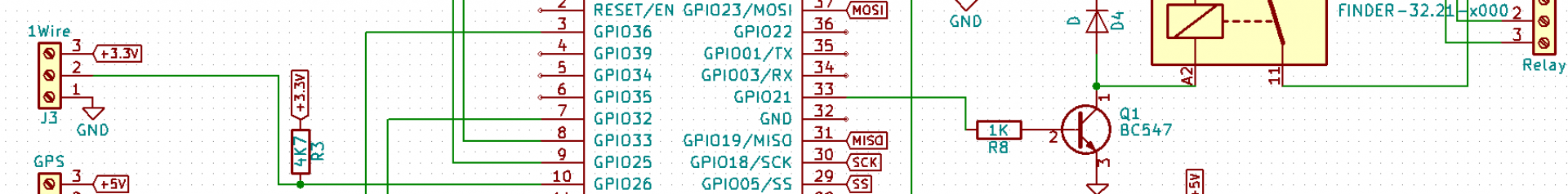
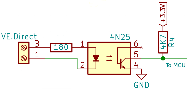
Although VE.Direct is basically RS-232, it uses different voltages. I read somewhere you can just solder a cable with a JST connector on one end and e DB9 connector on the other, but my multimeter tells me otherwise. Apart from that, some devices run at 3.3V (BMV-700), others at 5V. To cope with this and eliminate the risk of damaging the Victron device or my microcontroller, I like to use an optocoupler for isolation, like this:
NOTE: The 1K value for R4 (that I used in the original version of my data logger) may not work in all cases. Several people have reported problems. Therefore you should use a 4,7K resistor for R4 instead.
The only disadvantage of using an optocoupler is that the signal will be inverted. Luckily, the ESP32 has an option to tell the UART the serial signal is inverted. If you use a different microcontroller you may need some circuitry to invert the signal (again).
Serial
The serial parameters are pretty straightforward:
- Baud rate: 19200
- Data bits: 8
- Parity: None
- Stop bits: 1
- Flow control: None
Protocol
The devices send out their data in readable text in the following format:
[newline][label]<tab>[value]
These ‘newlines’ are actually carriage returns followed by a newline, so 0x0D, 0x0A. This is something to keep in mind if you are using something other than Windows to read the input. The lines are grouped into blocks. The device sends out a block every second. Blocks are separated by an empty line and every block has a checksum (more on that later).
Let’s take a look at the output from a BlueSolar MPPT 100|30 rev2:
PID     0xA04A
FW      116
SER#    HQ1750YFN5R
V       27690
I       4400
VPV     31300
PPV     125
CS      3
ERR     0
H19     6741
H20     55
H21     166
H22     106
H23     318
HSDS    84
Checksum        j
As you can see, some labels are clear, others are somewhat cryptic to say the least. You will find their meaning as well as the units used in the second column in the documentation. You will also find which labels are sent out by which device. Obviously, different devices send out different labels, although there is some overlap. If different devices send out lines with the same label, the meaning (and the units) will be the same.
Some devices divide their variables over more than one block. In that case, you will have to read all the blocks in order to get all the variables. Each block will have its own checksum. After the first block, a blank line line is sent, followed by a block of a different type, containing the rest of the variables. I am not aware of any devices sending out more than two different block types at this time, but in theory, it is possible. When all different block-types are sent, the cycle starts all over again, starting with the first block type. The first block of a sequence can be recognized by the fact that it starts with the PID number (Product ID). Be aware that there will still be a one-second interval between the blocks, so if you use some sort of timeout while reading your serial port, make sure there is enough time to read all the blocks (and possibly wait for the first block in the sequence). To clarify, here is the output from a BMV-702.
PID     0x204
V       25803
VS      11576
I       -897
P       -23
CE      -1719
SOC     997
TTG     14400
Alarm   OFF
Relay   OFF
AR      0
BMV     702
FW      0307
Checksum        ▒

H1      -167452
H2      -1719
H3      -124118
H4      3
H5      0
H6      -2544565
H7      14173
H8      31779
H9      9178
H10     13
H11     0
H12     0
H15     1
H16     15911
H17     4106
H18     9664
Checksum        L
Checksum
Because the communication sometimes may get corrupted (especially in electrically noisy environments), each block contains a checksum. To make sure you heard what the device meant to say, it’s a good idea to validate this checksum. After all, wrong readings are worse than no readings at all. The checksum is calculated over the entire block, including the line starting with Checksum, and including the newlines.
To calculate the checksum you have to add up all the ASCII values. The result of that should be a multiple of 256. Or, if you sum it all up in a byte variable, the result should be 0. The checksum character is used to make sure of that. That means that the checksum is not necessarily a printable character.
An example in (Arduino) C++:
byte calcChecksum(String input) {
  uint8_t checksum = 0;
  for (int i = 0; i < input.length(); i++) {
    checksum += input.charAt(i);
  }
  return (checksum);
}