Since we’re carbage running as team Fred & Wilma, I figured we needed a soundboard. You know, Fred screaming “Wilmaaaa!”, the distinctive sound of Fred driving off in his car, Wilma laughing, etc. And some of these sounds should be played automatically, for instance when disengaging the handbrake.
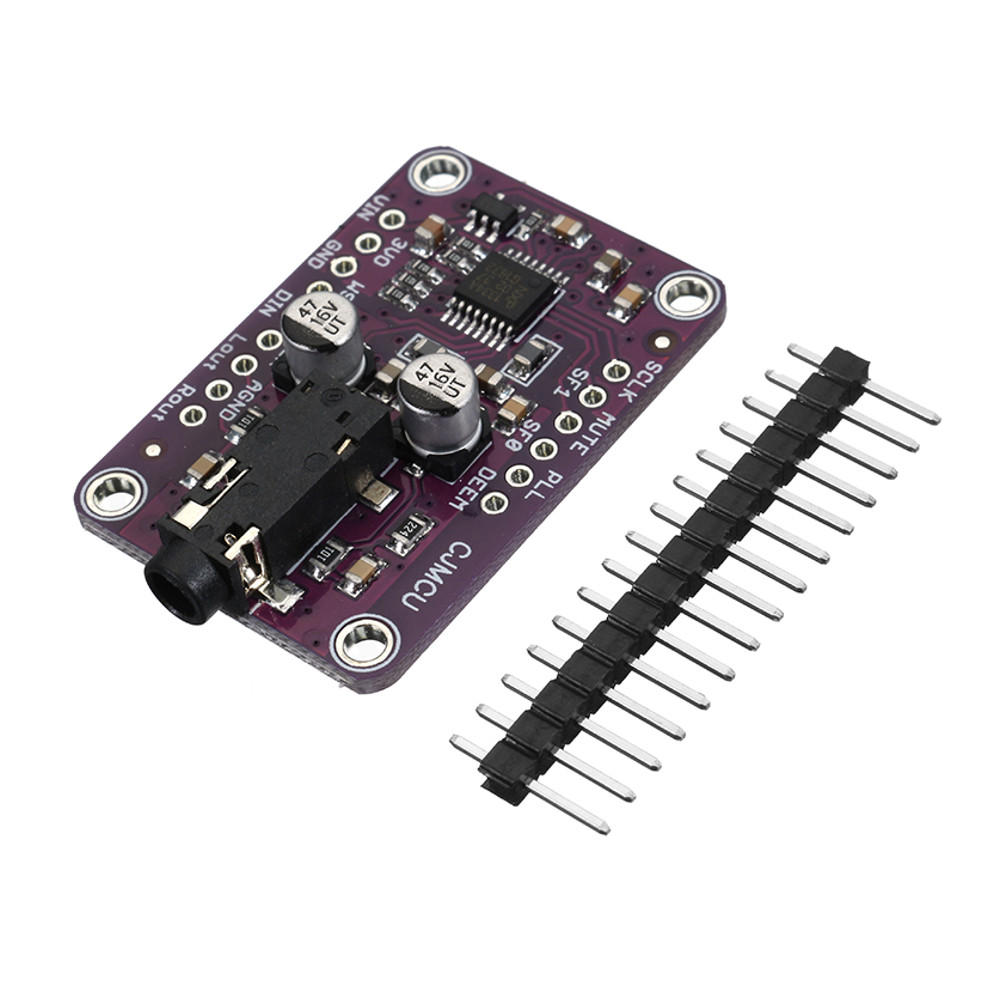
I experimented with playing audio directly trough one of the ESP32’s DACs, but for some reason, I could not get the sound quality up to an acceptable level. If you want to take a shot at it: be my guest. You will find some pointers here. I choose a different solution: An external audio decoder board based on the UDA1334A chip. It takes data via I2S and can be bought from Aliexpress, eBay, Banggood, etc.
Here are the most important features:
- Voltage regulator, so the board can be powered directly from the car battery (with reverse polarity protection).
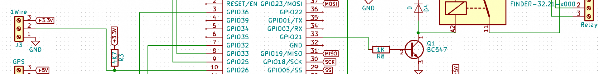
- Two 12V tolerant digital inputs. These can be used to trigger the playback of a sound if the lights are switched on, the handbrake is disengaged etc.
- An analog input. This can be used to connect multiple switches. If every one of these switches has a resistor in series, the software can tell which one is pushed by reading the value of the analog input.
- A relay. This may come in handy to power on an external amplifier or to switch on some light effects whenever a sound is being played.
- Audio output, of course. In stereo.
- ESP8266 MCU. Since the audio decoding is now done by a dedicated chip, there is no need to use the ESP32. The ESP8266 is fast enough. The NodeMCU boards have 4MB of flash memory. 1MB will be used for the software, the rest is available for audio samples.
I have a working proof of concept, I am still working on the software. Currently, the software plays only .WAV files and I would like it to handle .MP3 as well. After all, 3MB of SPIFFS is not a lot if you are using uncompressed audio files.
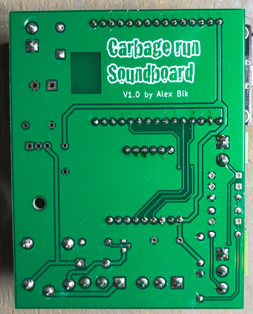
A few notes on the PCB design:
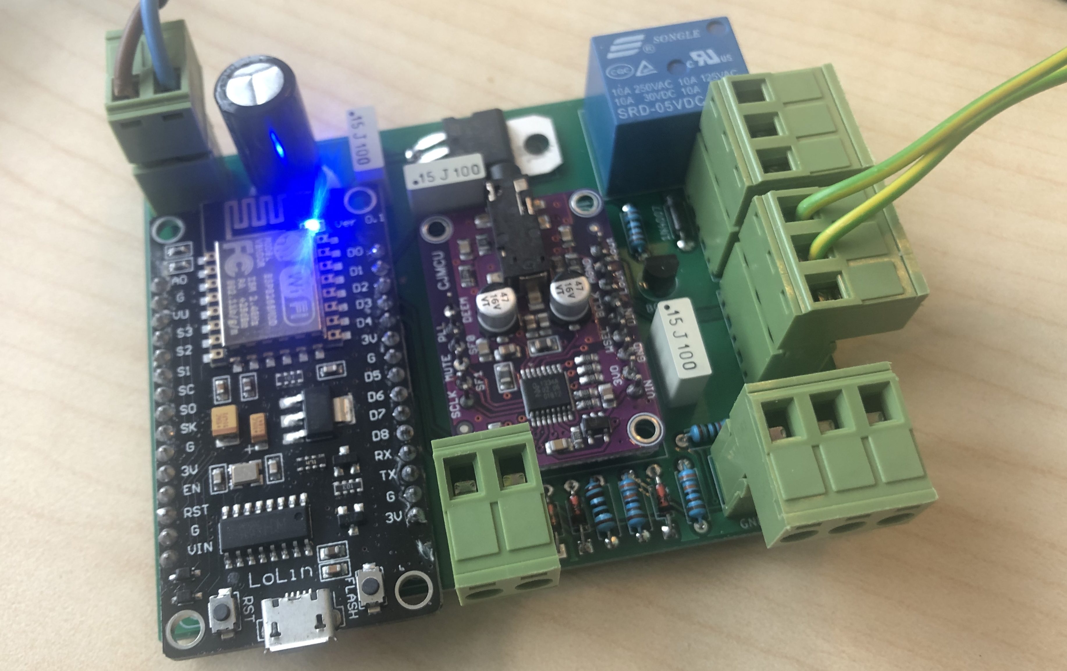
- The NodeMCU dev board appears to be available in two variants. One has a square FTDI chip, the other one has a rectangular one. The footprint used in the design is for the smaller ones with the square FTID chip. The larger one will fit (and the connections are all in the same place), but the electrolytic capacitor is in the way. If you mount the NodeMCU board first, you can mount the capacitor a little bit to the side. As you can see in the picture above, that is what I did, because I didn’t realize the footprint I used was for a differend NodeMCU board than the one I had.
- I used a cheap UDA1334A breakout board I got off eBay. It seems to be the same as Adafruit’s “UDA1334 I2S DAC”. The only difference I noticed is the color of the PCB. Both versions should work.
- I used the breakout board rather than the chip itself (and some discrete components) in my PCB design to make it easier to assemble.