Author: alex

As you may or may not know, I have a bus that I use as an RV. I use two large lead-acid batteries with a capacity of 280Ah each to power the lights, the fridge, the coffee maker, etc. The batteries are wired in series to give me 280Ah at 24V. As the batteries are starting to degrade to the point that it’s getting annoying and prices for Lithium-based batteries are coming down, I decided to ditch the lead-acid batteries and go for lithium instead. More specifically, Lithium iron phosphate (LiFePO4)

You can’t just wire up a couple of lithium cells in series and go camping. They need some additional stuff to keep them happy and safe. Since I like to fiddle with electronics and I certainly don’t mind saving some money in the process, I’m building the battery myself.

In this post I will explain which components I’ll use and why.
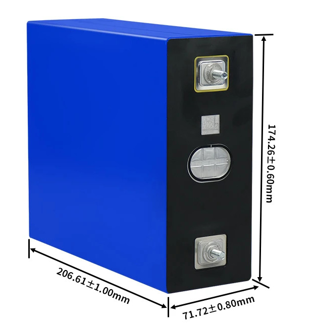
The cells

The 320Ah LiFePO4 cells I ordered

Lithium-based batteries can be discharged almost completely without damaging them, while lead-acid-based batteries need to be kept above 50% state of charge (SOC). Disobeying this rule will decrease the number of usable charge/discharge cycles. Lithium-based batteries also have the advantage of being lighter, smaller, and more efficient.

Lithium batteries come with some disadvantages as well. They’re more expensive, require additional electronics, some types can be dangerous if mishandled, and you can’t charge most types below freezing temperatures.

There are three main types of lithium batteries: Lithium-ion, lithium-iron-phosphate (LiFePO4), and lithium-titanate-oxide (LTO). All three types have their own characteristics, pros and cons.

  • Lithium-ion is relatively cheap. The life expectancy is the lowest of all lithium-based battery chemistries at 300 to 500 full cycles, making the cost per cycle not that great. The real showstopper for me is the fire hazard though. Lithium-ion batteries are infamous for their tendency to spontaneously catch on fire if mishandled. To make it worse: A lithium-ion fire is very hard to put out because li-ion cells produce their own oxygen while burning. Not something I want to be using in my RV.
  • Lithium-titanate-oxide (LTO) cells have a great life expectancy, as much as 20000 cycles. They can be charged in freezing temperatures and are almost impossible to set on fire. Sounds like the ideal battery chemistry, right? Unfortunately, all these advantages come at a cost. LTO cells are about four times as expensive as LiFePO4 cells. Even though the price per cycle is OK, the long life expectancy is not really an advantage as these cells would probably outlive my RV (and me).
  • Lithium-iron-phosphate (LiFePO4) cells have a life expectancy of up to 6000 cycles. Prices have come down significantly over the last year or so, and last but not least: They don’t ignite or explode. There are some more nerdy advantages like their stable output voltage, but that’s not really important.

One disadvantage all lithum-based batteries have is the need to protect them from high/low voltages, and high/low temperatures. You must also keep all individual cells in the pack at the same voltage. Fortunately, all this is now easily taken care of by one of the many battery management systems (BMS) you can now buy at reasonable prices. More on that topic later.

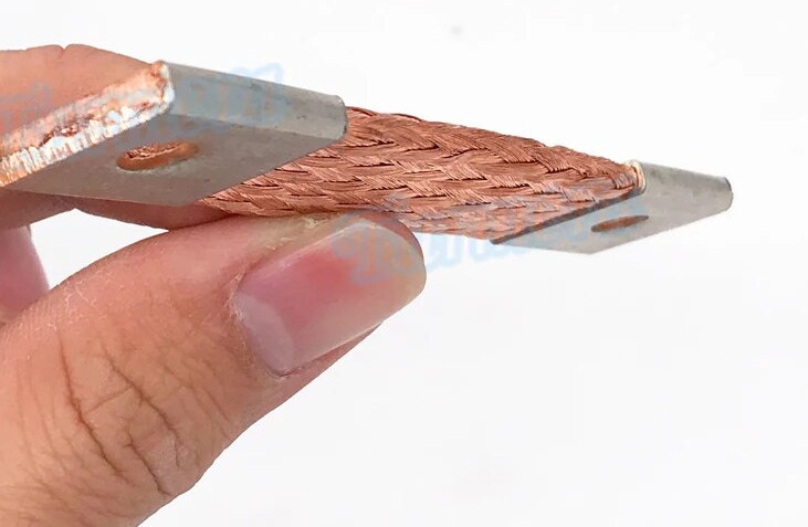
I ordered 8 320Ah LiFePO4 cells and some flexible busbars to connect them in series.
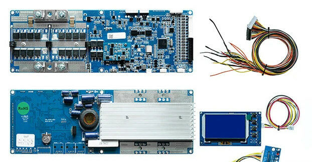
The BMS

A BMS is responsible for the well-being of the individual cells in a battery. In the case of LiFePO4 cells, this means:

  • Make sure the battery can’t be charged below freezing. It’s okay to draw power from cold cells, but an attempt to charge them while frozen will damage the cells instantly.
  • Protect the cells from overheating.
  • Protect the cells from over-discharging by switching off the load if the cell voltage drops below 2,5V.
  • Protect the cells from overcharging by switching off the charger if the cell voltage reaches 2,65V.
  • Balance the cell voltages to make sure all cells are equally charged.

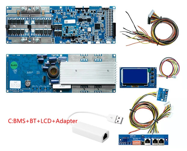
There are many BMS-es that offer these features. The main reason I chose the Seplos BMS V3, is because it can communicate with my Victron Cerbo GX. This allows me to really integrate the battery into my energy system and let it control my MPPT solar charge controller, among other things. It’s affordable, able to handle a decent amount of current (150A) and according to Andy over at the Off-grid garage, it works great if you use the latest software.

This BMS should also be able to control a battery heater. I have to figure out how to hook that all up when it arrives. The BMS will only turn on the heater if the cells are too cold and an attempt is made to charge the battery. Heating up the battery when it’s not going to be charged anyway is just a waste of energy. That’s why I didn’t want to use a thermostat.

Heaters

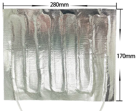
I already mentioned that LiFePO4 cells can not be charged below freezing. I’m adding a couple of heaters to the battery pack to overcome that limitation. The heaters will be hooked up to the BMS, which switches them on if an attempt is made to charge the battery while it’s frozen. When the battery is heated up sufficiently, the BMS will automatically switch off the heaters and allow charging.

Breaker

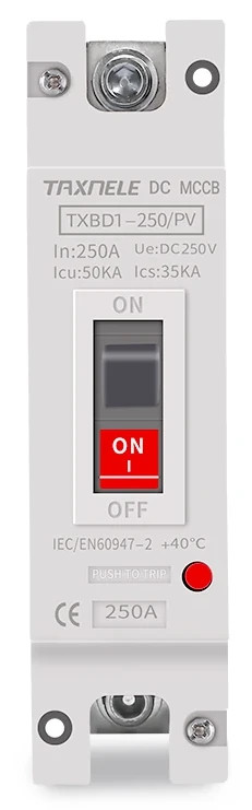
Lithium cells can deliver enormous amounts of current: The maximum allowed discharge current is 300A, although the BMS I chose is limited to 150A. The impedance of each cell is less than 0.25mΩ according to the specifications, which means that the short circuit current of a charged cell can be thousands of amps. That’s not good 🙂 I’ve ordered one of these breakers to make sure the current stays below 150A.

Terminals

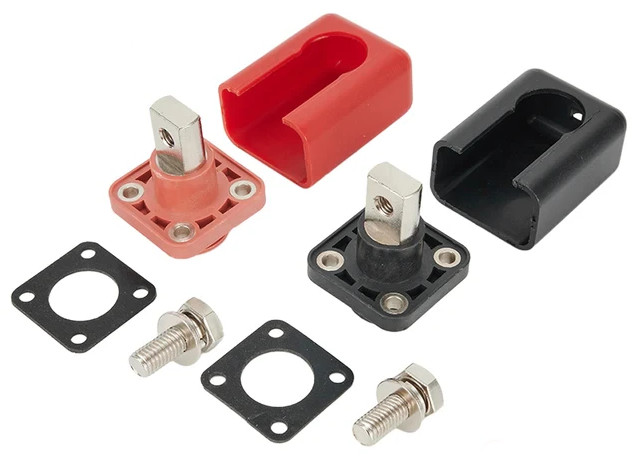
I wanted to have some neat battery terminals to mount in the box. I have to connect the finished battery one way or another. These ones can carry 200A and come with covers.

Torque wrench

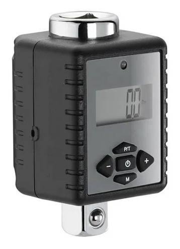
The nuts on the cells need to be torqued to specification. No more than 8nm (5.9 lbf · ft) it says in the manual, so 5nm (3.7 lbf · ft) should be fine. I don’t want to over-tighten the nuts. The studs in the cells are aluminum. I’ve already seen people (on YouTube) rip the threads out. I own a torque wrench, but it’s a big one. It’s not suitable for small nuts like this. That’s why I ordered this one.

That’s it!

Well, almost. There’s some small stuff I’ve ordered like self-adhesive foam pads, but nothing really worth mentioning. So now it’s time to practice my patience and wait for all the parts to be delivered.

In the meantime, I will think about the mechanical part of this project. How to build the casing, where to position the terminals, the BMS display, the breaker, etc.

Under cover Volvo

The last thing I wrote about the car is that the exterior was almost finished. Then COVID happened, the Carbage Run got postponed (twice) and the car sat under a cover for a little over two years.

Vinyl wrap discoloration

We were a bit disappointed (to say the least) when we found what these two years did to the vinyl wrap, even though the car was under a cover for the entire time. The once orange vinyl faded to yellow-ish, like the orange juice at a cheap hotel’s breakfast buffet. Some parts came loose and it shrank.

We also had a flat tire. It seemed it had been flat for quite some time and it needed to be replaced. The battery was obviously dead, too. The headliner also came loose. It didn’t just sag a little, it was completely loose. So we ended up removing it from the car, glueing it back on and mounting it again.

When removing the cover, we found two kittens underneath. Probably somewhere between one and two weeks old. Their mother came to get one of them, but she left the other. We called in professional help and we hope to be able to adopt him/her in about two months.

Kittens
Kittens found under the car

I like to repair broken electronics. I buy (or just collect) broken TVs, subwoofers, amplifiers, and the occasional power tool. I repair and sell them. Or throw it away if the item is (economically) beyond repair. It is a nice way to spend my time, especially since I now have more of that for obvious reasons. So when a friend told me a while ago his (rather expensive) subwoofer stopped working, I volunteered to take a look at it.

It looked like a straightforward problem. The unit gave no sign of life whatsoever and it had a blown fuse. Blown fuses are typically the result of a malfunction, rather than the cause. This fuse was not just blown, it was completely black, indicating something was shorting out.

After opening the unit up, it didn’t take me very long to diagnose the problem. The Switched-Mode Power Supply (SMPS) had a faulty rectifier diode in the secondary circuit which, in turn, led to the early demise of another diode and two MOSFETs. Both MOSFETS were shorted internally, explaining why the fuse was black. I ordered the parts on eBay (the local electronics shop was closed due to COVID, or at least I thought it was) and put the subwoofer aside for now.

When the parts arrived, I was confident the subwoofer would soon be in working order again. I was wrong. After replacing both diodes, MOSFETs, and the fuse I slowly turned up the voltage using my variac until the magic smoke escaped. What happened?

One of the capacitors in the secondary circuit nearly exploded. The good news was the SMPS was apparently working again, but why did the capacitor die? Apart from old age and/or bad quality, there are really only two reasons for an electrolytic capacitor to blow: Too much voltage or reversed polarity. My muli meter indicated the latter.

I had no schematic of the SMPS, nor could I find it online. So I had to reverse engineer it. Luckily the secondary part (where the problem obviously was) was simple. Basically, just the secondary winding of the transformer (the center of it connected to ground) and a full bridge rectifier made up out of two double ultra-fast recovery diodes in a TO-220 casing.

At this point, it was apparent to me both diodes should be different. But both had the same type number printed on them (MUR1620CT) and both had the same symbol printed just above the leads. Two diodes with their cathodes towards the middle pin of the TO-220 casing. That must be incorrect. But how is that possible? Before it died, the unit had worked for quite some years.

I was confuzzled. The power supply unit couldn’t have worked when both double diodes had their cathodes connected to the center pin. One of them should have the anodes in the middle. I decided to put the ones I took out under the microscope again and take another look.

That’s when I found out one was a MUR1620CT, the other one was a MUR1620CTA. When I first looked at the diodes to identify them, I totally missed the last A on the second one. The type number was the same, the symbol below the type number was the same (two diodes with their cathodes connected in the middle), so I figured both diodes were the same. They weren’t. According to the datasheet, the ‘A’ indicates the anodes are connected to the center pin, not the cathodes. That made a lot of sense.

I ordered some parts again and I’m quite sure the problem will be solved after replacing the diode and the electrolytic capacitor.

So, lesson learned: Do not trust schematic symbols printed on components.

This is what a proper MUR1620CT / MUR1620CTA pair looks like. Note the different symbols on the CTA version:

I have been looking for a good way to measure the amount of propane left in the tank in my RV. It turns out the manufacturer of the tank sells a gauge that can be easily fitted to the tank by replacing the old, non-electric one. How the sensor works is beyond the scope of this blog, what’s important is that the sensor has a variable resistance: 0 Ohms means the tank is empty, 90 Ohms means the tank is full (at 80%).

Of course, the manufacturer sells a display as well, but I wanted to connect the tank level sensor to my already existing ESP32-based logger. So I needed a way to measure resistance with a microcontroller. The most common and easy way is by pulling up an analog input of the controller and connecting the sensor between the analog input and ground, like this:

R2 is the sensor. It has a value between 0 Ohms and 90 Ohms. In order to be able to use the full range of the ESP32’s Analog to Digital Converter (ADC), Ohm’s law dictates that R1 should be 46 Ohms. We need 3.3V over R2 if it is at its maximum value of 90 Ohms. Therefore we need a current of 3.3/90 = 36.7mA. The voltage over R1 should be 1.7V (5V – 3.3V), so the value for R1 needs to be 1.7/0.0366 = 46 Ohms.

This solution is easy and cheap, but it has the disadvantage that the voltage at the analog input pin of the ESP32 (and thus the measured value in the software) is not linear to the value of R2 and therefore not linear to the amount of propane left in the tank.

This is due to the fact that if R2’s resistance changes, the current flowing through both resistors changes as well. This becomes clear if you look at the table below:

Tank levelResistanceVoltage% of voltage
0%0 Ohms0V0%
25%22.5 Ohms1.648%
50%45 Ohms2.472%
75%67.5 Ohms2.988%
100%90 Ohms3.3V100%
Output voltages of the voltage divider network at different tank levels.

As you can see, the behavior is not linear at all. Of course, this could be fixed in the software running on the ESP32, but the non-linearity makes the readings on one end of the range less accurate than on the other end.

Since the problem lies in the fact that a change in the resistance of R2 does also influence the current flowing through the circuit, I decided to solve this issue by using a constant current source. Building one is easier than you might think. Take a look at this circuit:

Measuring resistance with the help of a constant current source.

For now, just forget about C1, C2, and D1. I will get back to those later. U1 is a standard voltage regulator. It regulates it’s output voltage to a constant 5V, regardless of the output current or input voltage. This means that the voltage across R1 will always be 5V. R1 has a fixed value, therefore the current through R1 will be constant as well. Since R1 and R2 are in series, this also results in a constant current through R2.

To calculate the value for R1 we use Ohm’s law again. We still need the 36.7mA current through R2 to get 3.3V at full scale. 36.7mA at 5V means 5/0.0367 = 136 ohms. I’d use the next higher available value because in practice the current will be a little bit higher due to U1’s own power consumption.

With the current through R2 now being constant, the voltage at the input of the ESP32 will be linear to the resistance of R2 and thus linear to the propane level in the tank.

So what’s up with C1, C2 and D1?

First the capacitors C1 and C2. They keep U1 from oscillating. D1 is added as a safety measure. Because of the voltage drop between the input and the output of U1, the supply voltage needs to be higher than 5V. I use 12V in this example, but anything between 7V and 40V is fine. If R2 is for some reason disconnected, this would cause a voltage of around 9V on the input pin of the ESP32, which will probably destroy it.

If you would like to learn more and fiddle around with Ohm’s law and voltage divider networks, take a look at this page.

Black spots

It has been quite a while since I last posted an update about our work on the Carbage run car. We did make quite some progress!

Vinyl wrap

We finished the orange vinyl wrap. Although it all looks peachy on the pictures, the wrap job didn’t go quite as planned. Partly because we never wrapped a car before, but also because the vinyl wrap I bought was really bad. When I ordered it, I didn’t feel like spending €600 on some decent vinyl (3M, Avery, VViViD) so I went for cheap no-name stuff that “only” cost me just under €200. That turned out to be a mistake. The foil can not stretch enough to wrap it around bumpers, it gets shiny very quickly if you apply heat (it basically melts), the adhesive is very bad (we had to redo some parts because the foil literally came off) and it discolored after sitting outside for just a couple of days. And it wasn’t even sunny. In retrospect, the €400 I saved wasn’t worth the extra work, frustration, and sub-optimal result. If I am ever going to wrap a car again, I will definitely go for one of the brands mentioned above.

Stickers

Stickers

Unfortunately, we didn’t have much luck with the stickers either. I wanted to have the name of the team on the car, the image of Fred and Wilma, Fred’s tie on the hood and the logos of our sponsors on the side. I had the stickers printed on transparent vinyl by some online print shop. They said they couldn’t print white, but since there wasn’t really any white in the design, I went ahead and placed the order. When the arrived it all looked fine. Until I removed the back sheet. I turned out that the colors they printed were not opaque, so effectively the stickers could only be used on a white background. What’s the use of transparent stickers if they can only be used on white? After complaining about it I got a refund and ordered the stickers elsewhere. When they arrived, the colors turned out to be wrong. I don’t know what happened, but it looked like the white they printed was blue. When I called them and send them an e-mail with a picture of the result they apologized and reprinted everything. The next day I finally had the stickers I wanted.

Rooftop tent

Rooftop tent

We wanted to have a rooftop tent on the car. During the Carbage run, we sleep at a different campsite every day and setting up and breaking down a regular tent every day is just too much hassle. A rooftop tent is ready to be slept in within 2 minutes. I checked Marktplaats (like the Dutch Craigslist) for a while. The rooftop tents on there were either too expensive, too far away or the seller was unresponsive (why place an ad if you are not going to respond?), but after a few months I found one that was exactly the type I wanted, it was not too expensive, not too far away and the seller responded quickly. I bought it the same day.

Black spots

Black spots

In the meantime, I ordered some vinyl wrap for the black spots. I choose the velvet option and that turned out very nice. It feels soft and it has a really deep matte black finish. I think it is the same stuff they use for airbeds. It feels the same anyway. Emmie started working on it. Getting the shape and size right is one thing. Distributing them evenly while avoiding the stickers and covering up the worst imperfections in the orange vinyl wrap all at the same time turned out to be quite a job. One she did very well!

Ever since we decided on the team name (Fred & Wilma) for the Carbage run, we have been thinking about how to make the Volvo look more like the Flintstone mobile. We thought about wrapping it in wood grain vinyl wrap, but we couldn’t quite figure out which part should be wrapped exactly and, equally important, what to do with the rest of the car. After some time we decided to wrap the entire car in orange vinyl wrap and make black stains on it (like Fred Flintstone’s outfit). And some printed stickers to pimp it up a little but more on that later.

We never wrapped a car before so we watched quite some YouTube howtos. We ordered some vinyl, a squeegee, borrowed a heat gun and started fiddling around with it. We probably made it more difficult by buying some (relatively) cheap no-name vinyl wrap rather than 3M, VViViD or Avery, but we can’t say for sure because we’ve never tried those.

A few weeks ago, I was browsing on one of those Chinese websites (I’m not mentioning names) when I came across some parking sensors. A set of 4 sensors, controller, display unit and a hole saw to make the necessary holes in the rear bumper would set me back only €15. The ’99 Volvo I bought for the Carbage run didn’t have any parking sensors and I was curious about this set, so I decided to order it.

A few weeks later, the package arrived and I installed it. The hardest part was to find a suitable route for the sensor cables. The rear bumper is filled with this foamy material, which makes it hard to get the cables through. Once that was done, I hooked up the controller to the reverse light wires. In that way, the sensors are only active when the car is in reverse. I put the display unit on the dash (I have yet to find a suitable place for it) and that was basically it. It just worked. So this is going to be a short post about €15 well spent 🙂

WordPress › Error

There has been a critical error on this website.

Learn more about troubleshooting WordPress.