I have been looking for a good way to measure the amount of propane left in the tank in my RV. It turns out the manufacturer of the tank sells a gauge that can be easily fitted to the tank by replacing the old, non-electric one. How the sensor works is beyond the scope of this blog, what’s important is that the sensor has a variable resistance: 0 Ohms means the tank is empty, 90 Ohms means the tank is full (at 80%).
Of course, the manufacturer sells a display as well, but I wanted to connect the tank level sensor to my already existing ESP32-based logger. So I needed a way to measure resistance with a microcontroller. The most common and easy way is by pulling up an analog input of the controller and connecting the sensor between the analog input and ground, like this:
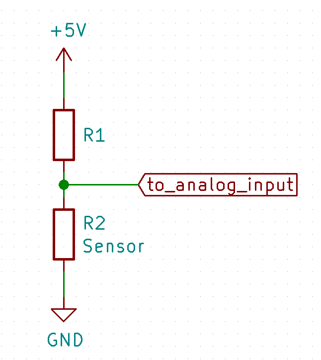
R2 is the sensor. It has a value between 0 Ohms and 90 Ohms. In order to be able to use the full range of the ESP32’s Analog to Digital Converter (ADC), Ohm’s law dictates that R1 should be 46 Ohms. We need 3.3V over R2 if it is at its maximum value of 90 Ohms. Therefore we need a current of 3.3/90 = 36.7mA. The voltage over R1 should be 1.7V (5V – 3.3V), so the value for R1 needs to be 1.7/0.0366 = 46 Ohms.
This solution is easy and cheap, but it has the disadvantage that the voltage at the analog input pin of the ESP32 (and thus the measured value in the software) is not linear to the value of R2 and therefore not linear to the amount of propane left in the tank.
This is due to the fact that if R2’s resistance changes, the current flowing through both resistors changes as well. This becomes clear if you look at the table below:
| Tank level | Resistance | Voltage | % of voltage |
| 0% | 0 Ohms | 0V | 0% |
| 25% | 22.5 Ohms | 1.6 | 48% |
| 50% | 45 Ohms | 2.4 | 72% |
| 75% | 67.5 Ohms | 2.9 | 88% |
| 100% | 90 Ohms | 3.3V | 100% |
As you can see, the behavior is not linear at all. Of course, this could be fixed in the software running on the ESP32, but the non-linearity makes the readings on one end of the range less accurate than on the other end.
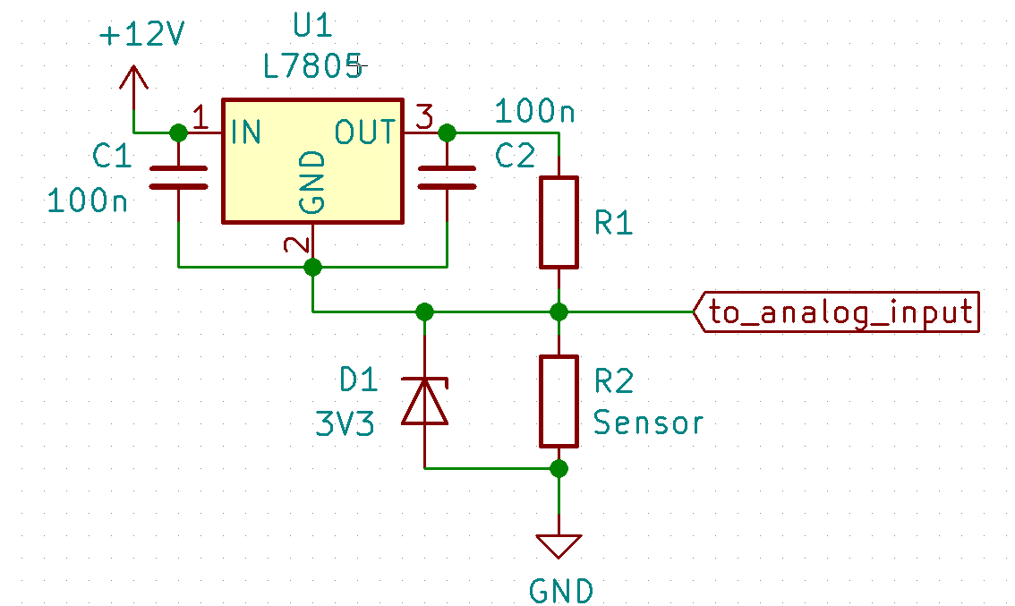
Since the problem lies in the fact that a change in the resistance of R2 does also influence the current flowing through the circuit, I decided to solve this issue by using a constant current source. Building one is easier than you might think. Take a look at this circuit:
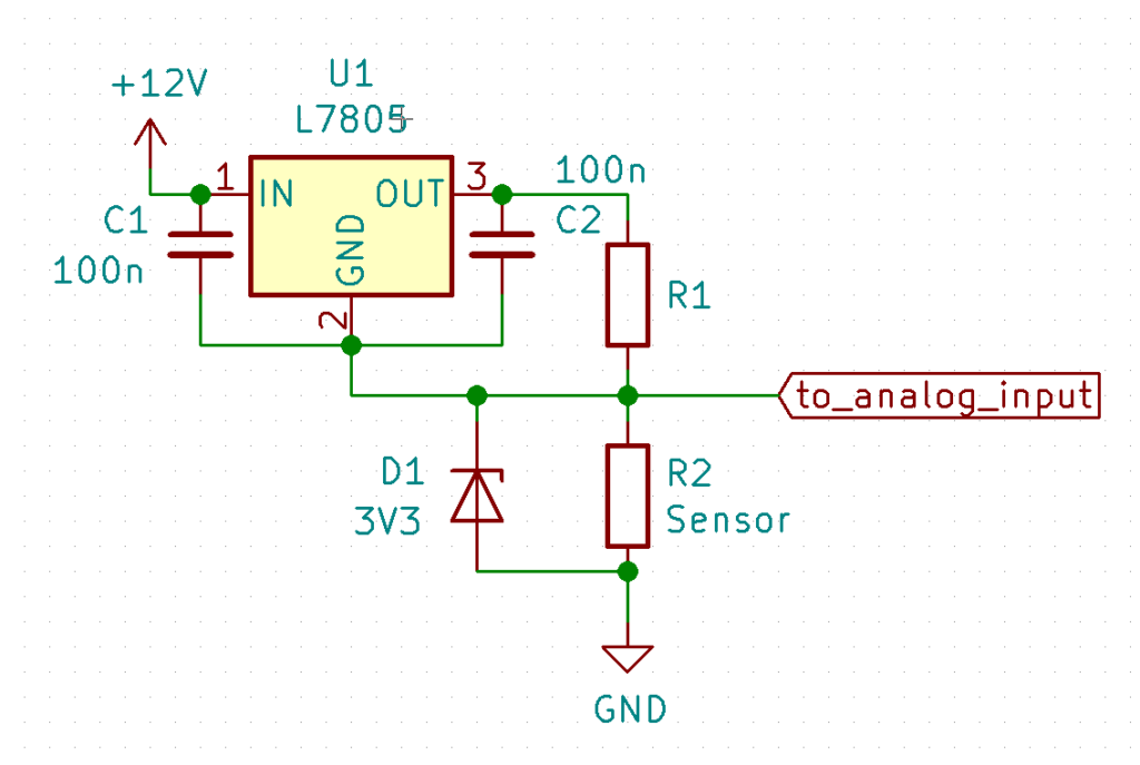
For now, just forget about C1, C2, and D1. I will get back to those later. U1 is a standard voltage regulator. It regulates it’s output voltage to a constant 5V, regardless of the output current or input voltage. This means that the voltage across R1 will always be 5V. R1 has a fixed value, therefore the current through R1 will be constant as well. Since R1 and R2 are in series, this also results in a constant current through R2.
To calculate the value for R1 we use Ohm’s law again. We still need the 36.7mA current through R2 to get 3.3V at full scale. 36.7mA at 5V means 5/0.0367 = 136 ohms. I’d use the next higher available value because in practice the current will be a little bit higher due to U1’s own power consumption.
With the current through R2 now being constant, the voltage at the input of the ESP32 will be linear to the resistance of R2 and thus linear to the propane level in the tank.
So what’s up with C1, C2 and D1?
First the capacitors C1 and C2. They keep U1 from oscillating. D1 is added as a safety measure. Because of the voltage drop between the input and the output of U1, the supply voltage needs to be higher than 5V. I use 12V in this example, but anything between 7V and 40V is fine. If R2 is for some reason disconnected, this would cause a voltage of around 9V on the input pin of the ESP32, which will probably destroy it.
If you would like to learn more and fiddle around with Ohm’s law and voltage divider networks, take a look at this page.