I like to repair broken electronics. I buy (or just collect) broken TVs, subwoofers, amplifiers, and the occasional power tool. I repair and sell them. Or throw it away if the item is (economically) beyond repair. It is a nice way to spend my time, especially since I now have more of that for obvious reasons. So when a friend told me a while ago his (rather expensive) subwoofer stopped working, I volunteered to take a look at it.
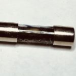
It looked like a straightforward problem. The unit gave no sign of life whatsoever and it had a blown fuse. Blown fuses are typically the result of a malfunction, rather than the cause. This fuse was not just blown, it was completely black, indicating something was shorting out.
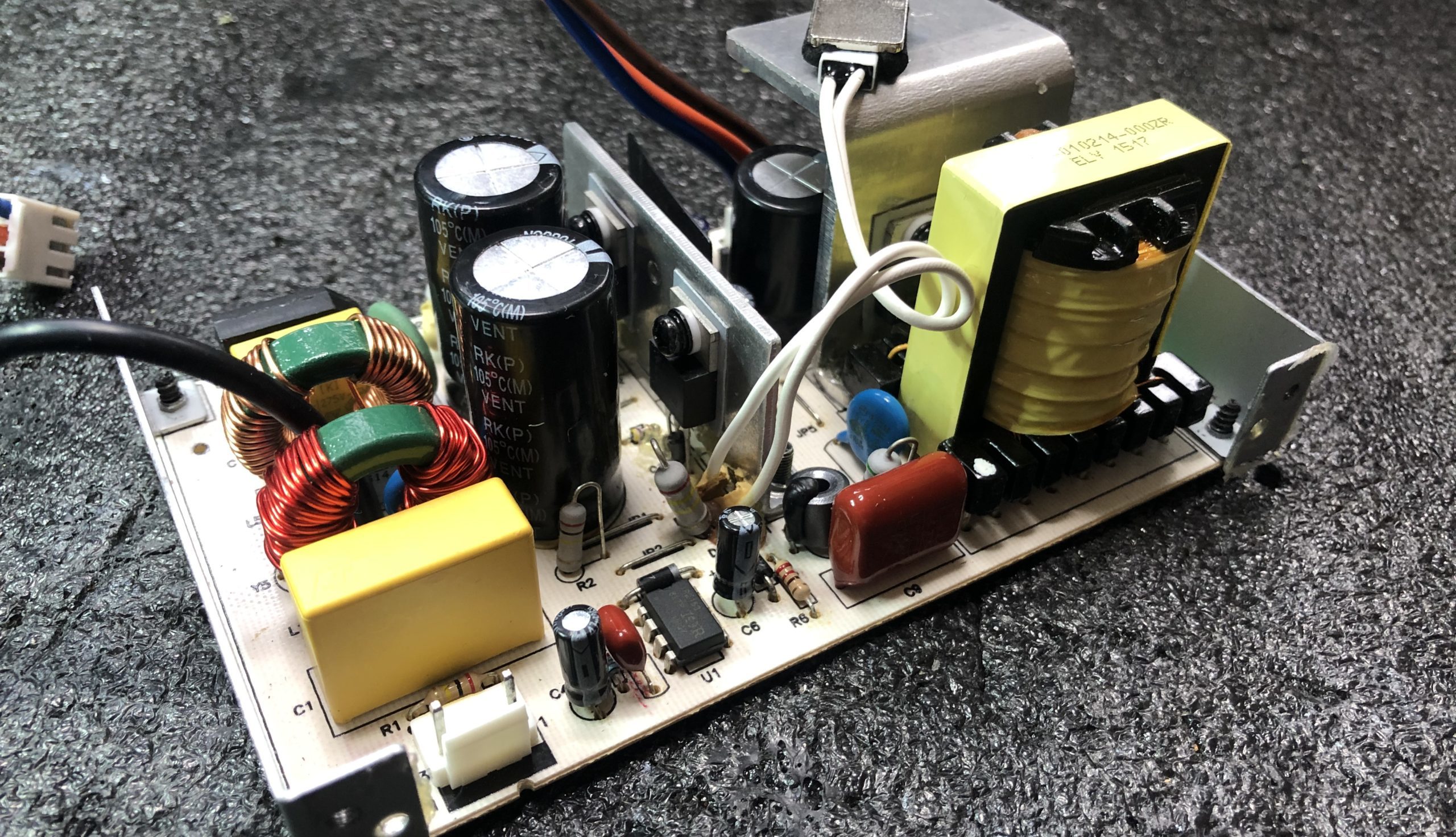
After opening the unit up, it didn’t take me very long to diagnose the problem. The Switched-Mode Power Supply (SMPS) had a faulty rectifier diode in the secondary circuit which, in turn, led to the early demise of another diode and two MOSFETs. Both MOSFETS were shorted internally, explaining why the fuse was black. I ordered the parts on eBay (the local electronics shop was closed due to COVID, or at least I thought it was) and put the subwoofer aside for now.
When the parts arrived, I was confident the subwoofer would soon be in working order again. I was wrong. After replacing both diodes, MOSFETs, and the fuse I slowly turned up the voltage using my variac until the magic smoke escaped. What happened?
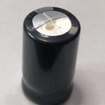
One of the capacitors in the secondary circuit nearly exploded. The good news was the SMPS was apparently working again, but why did the capacitor die? Apart from old age and/or bad quality, there are really only two reasons for an electrolytic capacitor to blow: Too much voltage or reversed polarity. My muli meter indicated the latter.
I had no schematic of the SMPS, nor could I find it online. So I had to reverse engineer it. Luckily the secondary part (where the problem obviously was) was simple. Basically, just the secondary winding of the transformer (the center of it connected to ground) and a full bridge rectifier made up out of two double ultra-fast recovery diodes in a TO-220 casing.
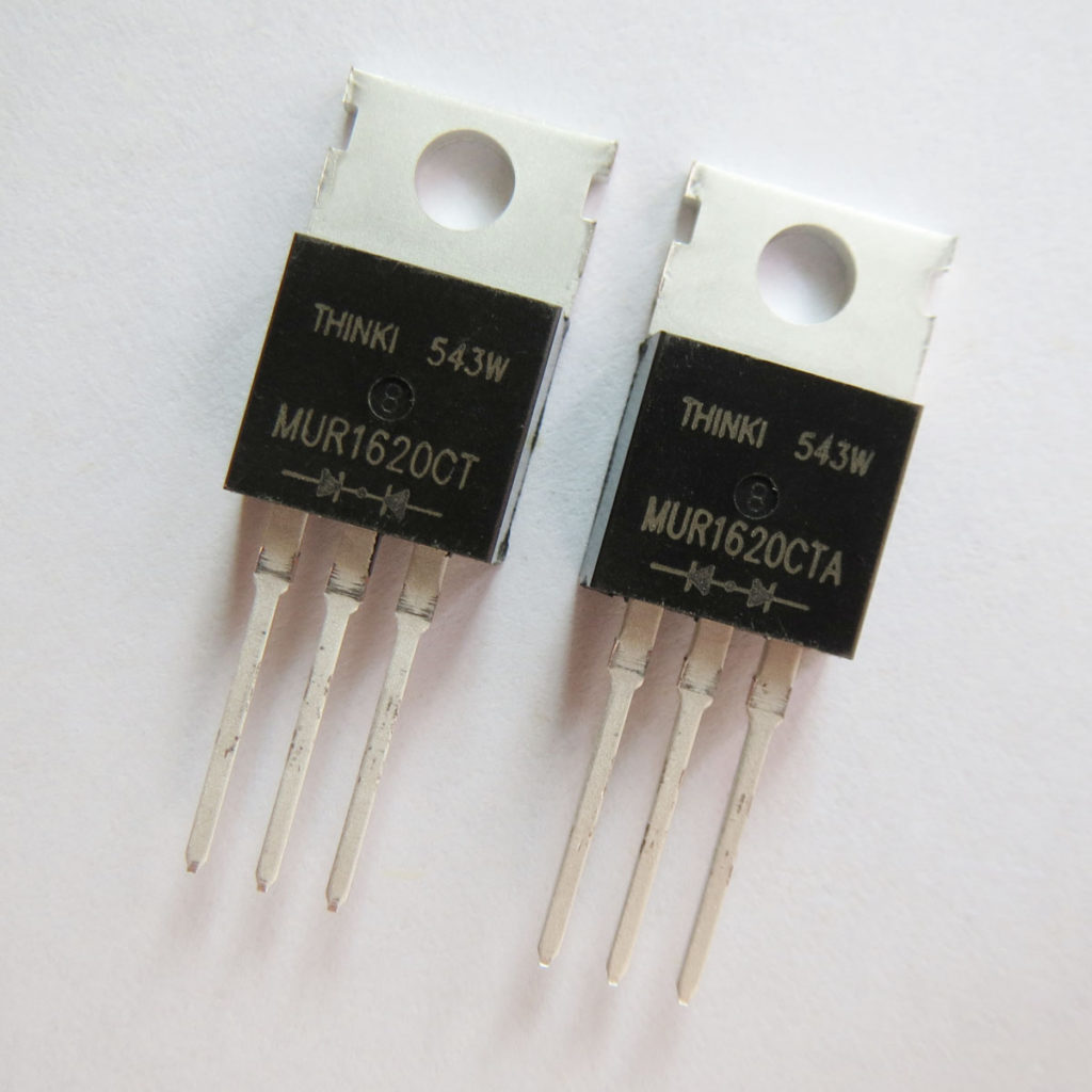
At this point, it was apparent to me both diodes should be different. But both had the same type number printed on them (MUR1620CT) and both had the same symbol printed just above the leads. Two diodes with their cathodes towards the middle pin of the TO-220 casing. That must be incorrect. But how is that possible? Before it died, the unit had worked for quite some years.
I was confuzzled. The power supply unit couldn’t have worked when both double diodes had their cathodes connected to the center pin. One of them should have the anodes in the middle. I decided to put the ones I took out under the microscope again and take another look.
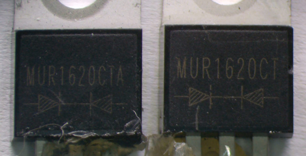
That’s when I found out one was a MUR1620CT, the other one was a MUR1620CTA. When I first looked at the diodes to identify them, I totally missed the last A on the second one. The type number was the same, the symbol below the type number was the same (two diodes with their cathodes connected in the middle), so I figured both diodes were the same. They weren’t. According to the datasheet, the ‘A’ indicates the anodes are connected to the center pin, not the cathodes. That made a lot of sense.
I ordered some parts again and I’m quite sure the problem will be solved after replacing the diode and the electrolytic capacitor.
So, lesson learned: Do not trust schematic symbols printed on components.
This is what a proper MUR1620CT / MUR1620CTA pair looks like. Note the different symbols on the CTA version: